
Ο ΔΙΟΛΚΟΣ ΣΤΟΝ ΙΣΘΜΟ ΤΗΣ ΚΟΡΙΝΘΟΥ
ΜΕΤΑΦΟΡΑ ΦΟΡΤΙΩΝ ΜΕΣΩ ΤΟΥ ΔΙΟΛΚΟΥ
Όπως έχουμε περιγράψει σε προηγούμενο κεφάλαιο, στον Δίολκο, έχει διασωθεί μια λίθινη επιφάνεια, σε επαφή με τη θάλασσα (Εικ.1, 2). Αποτελείται από εφαπτόμενους δόμους, χωρίς να συνδέονται μεταξύ τους με μεταλλικούς ή άλλους συνδέσμους. Η άνω επιφάνεια αυτών, είναι συνήθως ορθογωνικής μορφής, με διαστάσεις οι οποίες ποικίλουν. Δημιουργούν επίπεδο με κλίση προς τη θάλασσα. Σ’ αυτό το επίπεδο -ράμπα ή γλίστρα- γινόταν η ανέλκυση ή καθέλκυση των πλοίων.
 |
| Εικ.1: Κάτοψη της ράμπας-γλίστρας, στο στόμιο της διώρυγας στον Κορινθιακό κόλπο. Πηγή: Walter Werner, Nautical Archeology 1997. |
 |
| Εικ.2: Ράμπα-γλίστρα στο στόμιο της διώρυγας προς τον Κορινθιακό κόλπο. Πηγή: Φωτογραφία Απ. Παπαφωτίου. |
Η τοιχοδομή αυτή είχε ύψος Η=1,25, μήκος 24,50 μ. και πλάτος 6,10 μ. Έφερε δάπεδο σε όλο το πλάτος και σε μήκος 18,70 μ. από το συνολικό των 24,50 μ. Στην τοιχοδομή αυτή κατέληγε ο ολκός, ο οποίος είχε μήκος μέχρι 24,0 μέτρα.
 |
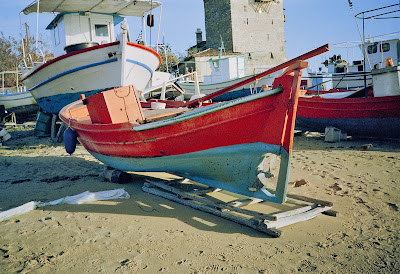
| Εικ.3: Καρνάγιο στη νέα Ρόδα Χαλκιδικής - «Βάζο». Πηγή: Φωτογραφία Απ. Παπαφωτίου. |
 |
| Εικ.4: Πρόταση ανελκύσεως σκάφους από τη ράμπα και τοποθέτηση αυτού στον ολκό που υπάρχει στην τοιχοδομή. Πηγή: Tony Kozelj, 2004. |
 |
| Εικ.5: Πρόταση ανελκύσεως σκάφους από τον ολκό στην τοιχοδομή, και στη συνέχεια, στη θάλασσα μέσω της ράμπας. Πηγή: Tony Kozelj, 2004. |
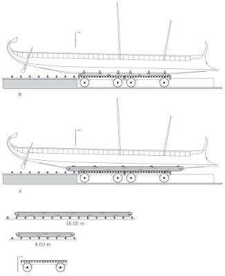 |
| Εικ.6: Ιδεατή αναπαράσταση μεταφοράς τριήρους σε διπλό ολκό και λεπτομέρειες ολκών. Πηγή: Tony Kozelj, 2004. |
Στην καθέλκυση, το σκάφος συρόταν με το «Βάζο» από τον ολκό το οποίο είχε τοποθετηθεί με αντίστοιχο τρόπο με αυτόν που είχε αφαιρεθεί κατά την ανέλκυση του σκάφους. Τραβώντας το «Βάζο», μεταφερόταν και το σκάφος εκτός του ολκού. Το τράβηγμα γινόταν από τους «εργάτες», οι οποίοι βρίσκονταν σε σταθερή θέση, όπως σημειώνεται στο σχέδιο. Στη συνέχεια, με προσεκτική χρήση άλλων «εργατών», το «Βάζο» έστριβε μαζί με το σκάφος και τελικά λάμβανε θέση κάθετη προς την ακτή, κατ’ επέκταση του κεκλιμένου επιπέδου (γλίστρα), το οποίο θα υπήρχε και στον Σαρωνικό κόλπο. Γλιστρώντας το πλοίο στο «Βάζο», αφού είχαν βγει τα πλαϊνά στηρίγματα, κατερχόταν από το κεκλιμένο επίπεδο στη θάλασσα. Η στροφή του συστήματος «Βάζου-σκάφους» γινόταν με χρήση «εργατών», με τη βοήθεια επιπλέον φαλαγγιών υπό μορφή εσχάρας. Τα φαλάγγια είχαν κάθετη διάταξη σε σχέση με το σκάφος, και δημιουργούσαν πλευρές εξαγώνου στο τεταρτημόριο του κύκλου της κινήσεως. Η αντίστοιχη τοιχοδομή και το κεκλιμένο επίπεδο (γλίστρα) στον Σαρωνικό κόλπο, δεν έχει αποκαλυφθεί τουλάχιστον μέχρι σήμερα.
 |
| Εικ.7: Μεταφορά σκάφους πάνω σε ολκό. Τομή μετά ενδεικτικών υψομέτρων. Πηγή: Tony Kozelj, 2004. |
 |
| Εικ.8: Καρνάγιο στη νέα Ρόδα Χαλκιδικής - «Βάζο». Πηγή: Φωτογραφία Απ. Παπαφωτίου. |
 |
| Εικ.9: Καρνάγιο στη νέα Ρόδα Χαλκιδικής. Πηγή: Φωτογραφία Απ. Παπαφωτίου. |
 |
| Εικ.10: Τοιχοδομή στην άκρη του Διόλκου στον Κορινθιακό κόλπο. Φωτογραφία Ν. Βερδελής, Αρχαιολογική Εταιρεία Ελλάδος. |
Βιβλιογραφία: "Ο ΔΙΟΛΚΟΣ ΣΤΟΝ ΙΣΘΜΟ ΤΗΣ ΚΟΡΙΝΘΟΥ" Απόστολος Ε. Παπαφωτίου, Πολιτικός Μηχανικός Ε.Μ.Π. Προλογίζει ο καθηγητής Ε.Μ.Π. Θεοδόσιος Π. Τάσιος.
Την ταινία “Δίολκος για 1500 χρόνια” μπορεί να την παρακολουθήσει κανείς στο: https://youtu.be/n--mWBKwBDI
Δρ. Απόστολος Ε. Παπαφωτίου
Πολιτικός Μηχανικός Ε.Μ.Π.
Οικονομολόγος Ε.Κ.Π.Α.
 |
| Εικ.11: Απόσπασμα από την ταινία “Δίολκος για 1500 χρόνια”. |
THE DIOLKOS ON THE ISTHMUS OF CORINTH
CARGO TRANSPORT ON THE DIOLKOS
As previous chapter has said, a stone pavement sloping into the sea has been preserved on the D (Fig. 1, 2). This is made up of paving blocks in mutual contact, but not held together by metal cramps or other ties. Their upper surfaces are usually orthogonal, of various sizes. They form a flat surface sloping toward and into the sea. The shops were hauled out and launched on this surface (ramp and slipway).
 |
| Fig.1: Plan of slipway-ramp at canal’s mouth on Corinthian Gulf. Source: W. Werner, Nautical Archaeology, 1947. |
 |
| Fig.2: Slipway-ramp at canal’s mouth on Corinthian Gulf. Source: Ap. Papafotioυ҆ s photograph. |
 |
| Fig.3: Boatyard at Nea Roda, Chalcidice Peninsula, showing paired Vasa. Source: Ap. Papafotioυ҆ s photograph. |
 |
| Fig.4: Hypothetical diagram of hauling out of ship on ramp and its placement on carriage awaiting on pavement of Diolkos. Source: Tony Kozelj, 2004. KEY: 1) Sea, 2) Entrance to Corinthian Gulf. |
After the “system” was emplaced the carriages could move they would have carried the least possible load. Consequently, if the vasa had a significant load, it would have to be removed. Thus the one or more props supporting the ship on a side were removed and, to keep it from toppling over, the ship was temporally supported by beams from the carriage on the ground. Then wooden pieces were placed so as to support the deck of the carriage. These props had a section face corresponding to the ship’s hull, and were single or double. The double props were held together by wooden rots. They were placed spaced every 4-5 m along the sip’s length and thus supported it.
 |
| Fig.5: Hypothesized lowering of ship from carriage to pavement and its subsequent launching by way of slipway-ramp. Source: Tony Kozelj, 2004. KEY: 1) Sea, 2) Entrance to Corinthian Gulf. |
In the same way the second main beam of the vasa was removed. Props supporting the ships other side were inserted. The carriage was thus freed of /from the considerable weight of the vasa and thereafter moved more easily. After the carriage together with the ship traveled the whole length of the D it arrived at the other sea. A corresponding platform like that at Poseidonia on the Corinthian Gulf would have existed on the Saronic Gulf also, at Skhoinous. The carriage and slip would have terminated their journey at that platform, which would have had about the same size as that on the Corinthian Gulf.
 |
| Fig.6: Diagrammatic representation of transport of trireme on double carriage-trucks and details of carriages. Source: Tony Kozelj, 2004. |
In Launching, the ship was pulled with the Vasa off the carriages, hich had been positioned in an orientation corresponding to that when the carriages was hauled out. By drawing the Vasa, the ships were transferred off the carriage. This was accomplished by the capstans, which were strongly fixed in position, as indicated on the diagram. Then, with successive use of other capstans, the Vasa were rotated along with the ship and finally took position perpendicularly to the shore, on the extension of the inclined surface (slipway), which also existed on the Saronic Gulf as well. Once the supporting props were removed from its sides, the ship slid over the Vasa from the inclined slipway into the sea. The “ship-vasa” system was rotated by means of capstans, and with the additional aid of rods arranged in the form of a grid. The rods were perpendicular to the ship and formed the sides of a hexagon on the quarter of the circle of movement. The corresponding platform and inclined plane (slipway) on the Saronic Gulf have not been found so far.
 |
| Fig.7: Transport of ships on carriage, cross sections with heights indicated. Source: Tony Kozelj, 2004. |
It should be noted that the termination of the D on the Saronic Gulf may have been perpendicular to the shorlone. If so, the platform – ramp system would have been simpler than that on the Gulf of Corinth.
 |
| Fig.8: Boatyard at Nea Roda, Chalcidice, showing large paired Vasa and their joining and spacing. Source: Ap. Papafotioυ҆ s photograph. |
 |
| Fig.9: Boatyard at Nea Roda, Chalcidice, showing small caϊque of gaϊta type hauled out after removal of Vasa. Source: Ap. Papafotioυ҆ s photograph. |
 |
|
Fig.10: Platform at Corinthian Gulf end of Diolkos. Photo by N. Verdelis, Archaeological Society of Greece. |
Bibliography: "THE DIOLKOS ON THE ISTHMUS OF CORINTH" by Apostolos E. Papafotiou, Civil Engineer N.T.U.A. (National Technical University of Athens). Foreword by Theodosius P. Tasios, Prof. at N.T.U.A. (National Technical University of Athens).
Animation film "Diolkos for 1500 years": https://youtu.be/3GtE0kfWDuU
Dr. Apostolos E. Papafotiou
Civil Engineer N.T.U.A.
Economist N.K.U.A.
 |
|
Fig.11: Animation film "Diolkos for 1500 years".
|
Δεν υπάρχουν σχόλια:
Δημοσίευση σχολίου